Background
The U.S. Army Corps of Engineers (USACE), Detroit District, is reviewing an application pursuant to Section 10 of the Rivers and Harbors Act of 1899 and Section 404 of the Clean Water Act for a Department of the Army (DA) permit by Enbridge Energy, Limited Partnership (Enbridge) (File LRE-2010-00463-56-A19) to construct a tunnel (the Line 5 Tunnel Project) that would house a replacement segment of Enbridge's Line 5 pipeline crossing the Straits of Mackinac (Straits) in Lake Michigan (see Figure 1). The primary Federal involvement associated with the proposed action is the discharge of dredged or fill material into waters of the United States, and the construction of structures and/or work that may affect navigable waters. Based on the potential impacts of the proposed project, the USACE intends to prepare an Environmental Impact Statement (EIS) in compliance with the National Environmental Policy Act (NEPA) to render a final decision on the permit application. The USACE is also preparing an Ethnographic/ Traditional Cultural Landscape Study as part of the EIS and its responsibilities under Section 106 of the National Historic Preservation Act.
Purpose and Need
The purpose of the project is to provide transportation of light crude oil, light synthetic crude oil, light sweet crude oil, and natural gas liquids between Enbridge’s existing North Straits Facility and Mackinaw Station, and to approximately maintain the existing capacity of the Line 5 pipeline while minimizing environmental risks.
The project purpose and need will be further developed following the Public Scoping Period.
Proposed Action and Alternatives
Proposed action and alternatives will be further developed following the public scoping period.
Project Plans
View Enbridge Line 5 Tunnel project plans here.
Description of the Line 5 Tunnel Project
The proposed Line 5 Tunnel Project is located within Mackinac County in Michigan’s Upper Peninsula and Emmet County within Michigan’s Lower Peninsula and includes subsurface crossing of the Straits. Line 5 currently crosses the Straits via two, 20-inch-diameter pipes that rest on or are anchored to the lakebed of the Straits (referred to as the “Line 5 Dual Pipelines” or “Dual Pipelines”). Enbridge is proposing to construct a tunnel underneath the lakebed of the Straits. This tunnel would house a new 30-inch pipeline for light crude oil, light synthetic crude oil, light sweet crude oil, and natural gas liquids, replacing the existing, dual pipelines crossing the Straits.
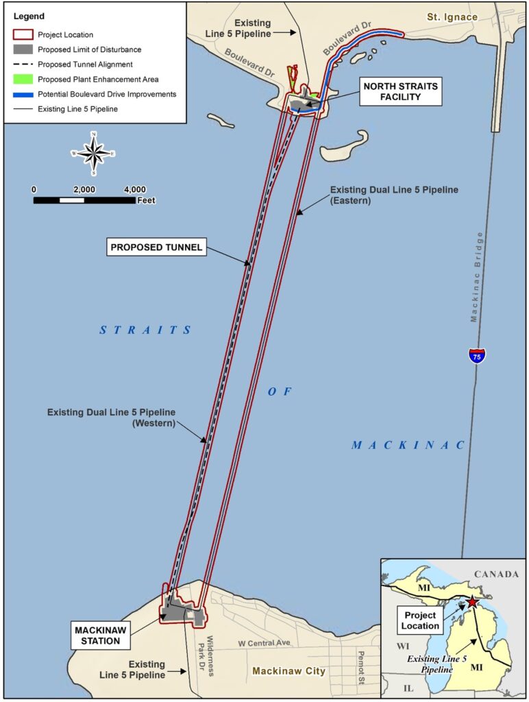
The proposed tunnel would cross below the lakebed of the Straits, connecting Point La Barbe in Michigan’s Upper Peninsula to McGulpin Point in Michigan’s Lower Peninsula in Mackinac and Emmet Counties, respectively. The distance between these two land points is approximately 3.6 miles and represents the shortest distance between Michigan’s Upper and Lower Peninsulas. The tunnel would extend as near as practicable to Enbridge’s existing Line 5 North Straits Facility located on the north side of the Straits to an opening point as near as practicable to Enbridge’s existing Line 5 Mackinaw Station located on the south side of the Straits.
Figure 2 shows the overall location of the proposed Project, including the location of the existing Dual Pipelines crossing of the Straits, the location of the existing North Straits and Mackinaw Station facilities (also referred to as the North Site and South Site, respectively), the location of the proposed Line 5 Tunnel crossing, and limits of disturbance associated with construction and operations of the proposed Project.
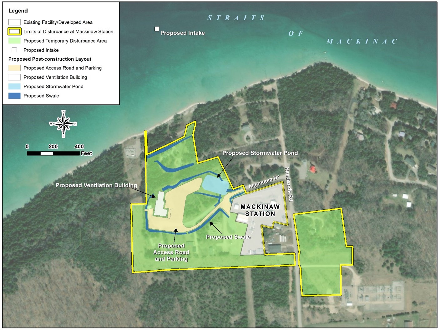
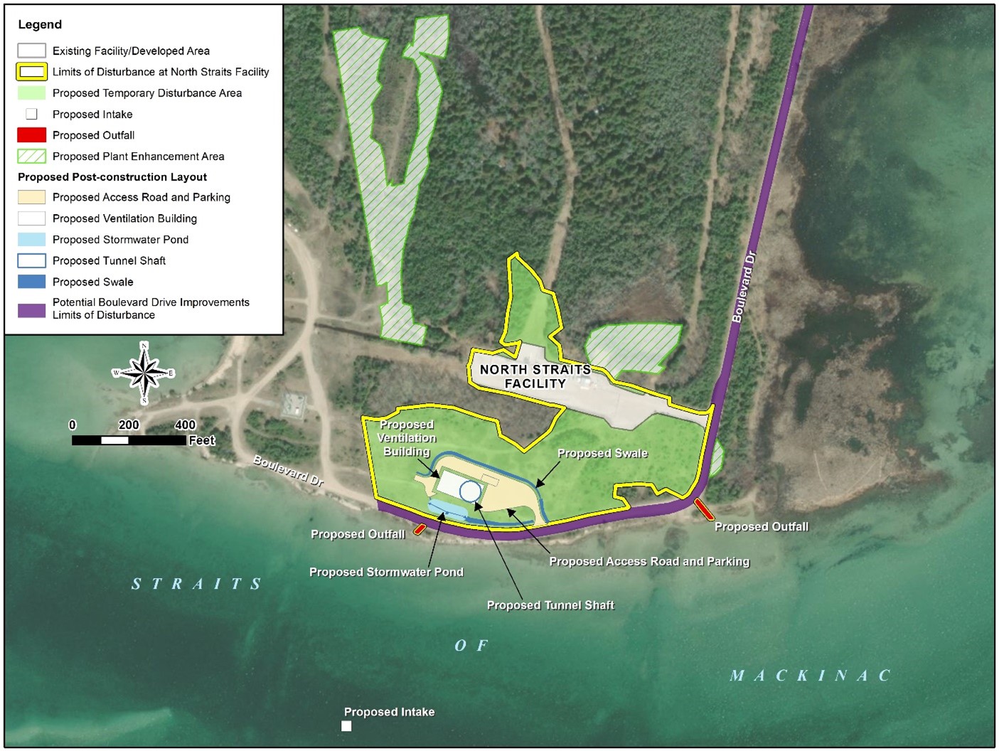
Figures 3 and 4 provide additional detail on activities proposed at the South and North sites including proposed temporary disturbance areas and proposed facilities necessary for tunnel operations. Figure 4 also includes additional “plant enhancement areas” identified for relocation of federally protected plant species currently located within the limits of disturbance for construction activities at the North Site.
The construction area within the proposed limits of disturbance would be covered in gravel fill. Proposed activities within the temporary disturbance areas include construction equipment staging areas and sediment and stormwater ponds. Activities at the South Site would include additional temporary facilities such as a project construction office building, parking for construction workers, a power substation and generator, spoil storage and management areas, a slurry and water treatment plant for treatment of excavated materials during tunnel construction, and a mechanic shop. Approximately 194 cubic yards of fill would be temporarily discharged into a wetland area north of the existing North Straits Facility to provide equipment access to a construction and staging area to the north of the facility. This fill would be removed upon completion of construction.
In addition, two water intake structures for construction of the tunnel would be installed offshore on each side of the Straits. Each intake structure would be marked with a surface buoy. The offshore intake structures and discharge pipe would be removed upon completion of tunnel construction. Treated water would be released into the Straits. A discharge pipe would be connected to the southern intake, which would be used intermittently to discharge treated wastewater into the Straits. Three outfalls would discharge stormwater or treated construction process water into the Straits from the shoreline, with two on the North Site and one on the South Site. A total of 78 cubic yards of aggregate fill would be discharged into wetland areas to construct the two outfalls on the North Site. Areas of temporary disturbance would be revegetated following construction. Figures 3 and 4 show the limits of disturbance for construction and the proposed post-construction site layout for the South and North Sites, respectively.
Construction and operations may also require improvements (road widening) to the existing Boulevard Drive, which provides access to the North Straits Facility (see Figure 2). Approximately 222 cubic yards of fill would be placed in six wetland areas totaling 0.08 acre on the landward side of Boulevard Drive to elevate and widen the road for construction equipment access.
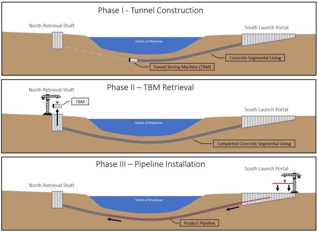
The tunnel would be constructed using a tunnel-boring machine. Except for the entrance points on either side of the Straits, the tunnel would be constructed entirely within the bedrock at depths between 30 feet and 370 feet beneath the lakebed of the Straits. Tunnel construction activities would result in removal of a total of approximately 364,000 cubic yards of material from underneath the lakebed.. The material would be transported to offsite disposal sites. A shallow launch portal between 400 and 1,000 feet long, 40 to 60 feet wide, and up to 50 to 80 feet deep would be constructed within the southern work area (McGulpin Point) and would serve as the entry point for the tunnel-boring machine. A circular shaft 70 feet in diameter and 150 feet deep would be constructed in uplands at the tunnel-boring machine exit point in the northern work area (Point La Barbe).
Once complete, the proposed tunnel’s inside diameter would be approximately 21 feet. Pre-cast concrete segmental lining would be installed as the tunnel is constructed, and the space outside the tunnel’s concrete lining would be filled with low-permeability grout. The new 30-inch pipeline would be installed within the tunnel and connected to the existing portions of the Line 5 pipeline. Upon completion, Enbridge proposes to decommission the existing submerged Line 5 dual pipelines crossing the Straits by purging, cleaning, and abandoning in place. Permanent facilities constructed in uplands would include stormwater ponds, outfall structures, access drives, and a ventilation building at each end of the tunnel (see Figures 3 and 4).
Portions of the project over which the Corps has regulatory jurisdiction include the structures and work associated with tunnel construction under the Straits of Mackinac, water intake structures in the Straits of Mackinac, and the discharge of fill material into wetlands. Proposed wetland impacts total 0.10 acre of permanent impact and 0.03 acre of temporary impact.


